
2024-06-26. Testing at summer QTH garden.
By the end of June, the family moved to the summer QTH at IN52 Maidenhead square. A small garden was available, and the antenna setup was adapted to the new situation. The AutoT 6.25 was installed on a tripod. 3 x 10 m, 2.5 mm2, wires were used as counterpoise. On top of it, a 5 m Aluminium radiator was mounted. It was composed of 5 x 1 m sections. Diameters (bottom to top) are 20 mm, 16 mm, 12 mm, 12 mm and 10 mm. Each section end was provided with brass inserts (male at bottom, female at top), to avoid galling and wear. Base section has a 7075 alloy insert, taped to M6, instead of the male one.
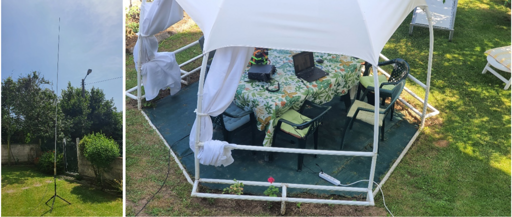
Summer QTH setup. Left: antenna. Right: “Shack”.
Initial SWR measurements were satisfactory. Tuning was possible from 7 MHz to 50 MHz. A few QSO were made in all bands. PSK reporter reception reports were good. Who could ask for more?
2024-06-30 ¿Funciona? ¿Sí? ¡No lo toques! (or, if it ain’t broke, don’t fix it!)… o quizá sí
Out of sheer curiosity [on the effect of parasitic inductance], it was decided to remove the ferrite bead inserted in the wire from UNUN output to the antenna stud (see section “2024-05-21 update: Adding parasitic inductance.”).
This was a bad move. SWR raised in 7 MHz, and FT-710 autotuner was unable to find a match. In this situation, it was considered interesting to get some insight on the result of adding some inductance (and not-negligible coiled wire length, too) between the output of the AutoT and the radiator.
For this purpose, it was used a home-built version of Yaesu’s ATAS-25 loading coil, made a few years ago. It has 40 mm diameter and 2.5 mm pitch. For increased reliability and easier construction, the coil was built with 1.5 mm2 (1.38 mm diameter) solid copper wire. The device allows inserting easily any number of turns between 0 and 58, and has a basic length of 337,5 mm for 0 turns. Equivalent length for 58 turns is 7.48 m, allowing tuning down to 7 MHz band when used with a 3 to 5 m radiator.
Inductance calculated with “Coil32” was 1.34 μH for 5 turns, 2.253 μH for 7 turns and 3.826μH for 10 turns. Equivalent added length were 0.953 m, 1.200 m and 1.569 m respectively. It must be noted that effects on SWR are a combination of both inductance and added length.
In this case, measurements are presented in tabular form (Table 6). Line graphs had too many entangled lines, making difficult the interpretation of results. Colours were graded according to SWR readings, green for low values and red for high ones, to highlight SWR differences according to each setup, and to allow identifying easily the best one.
Table 6: summary of SWR measurements by band and loading coil settings.
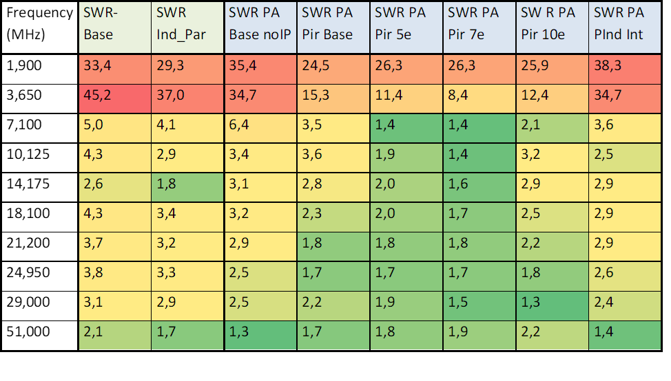
The two fist columns show measurements made at home QTH with a 3.88 m radiator, before (SWR-Base) and after (SWR Ind_Par) adding the extra parasitic inductance.
Column marked “SWR PA Base noIP” corresponds to measurements made with a 5.0 m radiator, no parasitic inductance added, no loading coil added.
Column marked “SWR PA Pir Base” corresponds to measurements made with a 5.0 m radiator, with the loading coil installed, all turns short-circuited.
Column marked “SWR PA Pir 5e” corresponds to measurements made with a 5.0 m radiator, and 5 turns in the loading coil.
Column marked “SWR PA Pir 7e” corresponds to measurements made with a 5.0 m radiator, and 7 turns in the loading coil.
Column marked “SWR PA Pir 10e” corresponds to measurements made with a 5.0 m radiator, and 10 turns in the loading coil.
Column marked “SWR PA PInd Int” corresponds to measurements made with a 5.0 m radiator, and the ferrite bead (BN-43) back in place, wire threaded through two apertures. Loading coil was removed.
It can be noticed that most favourable values were 5 and 7 turns, with around 2 uH inductance and 1.0 m added length. No surprises!
2024-07-04: Final fireworks
After the above tests, the ferrite bead was reinstalled, and operation from 7 to 50 MHz was again possible. Operating in FT8 at full power (100 W) went smoothly for some days, with short periods of activity at the beginning and the end of the day, sometimes after lunch. No big issue was detected. The AutoT 6.25 felt warm at the end of each session, but not too much.
However, after a long FT8 session in the evening of the 4th of July, the antenna started to tilt, and it felt down to the ground. At first, it was thought that the cause was the wind (the antenna was only held by the tripod, with not too ample base).
But a closer scrutiny brought a different picture. AutoT 6.25 felt warmer than usual. So it was open for inspection. What was found was a very hot core. So hot it was that it was fused to the wall of the enclosure, charring it.
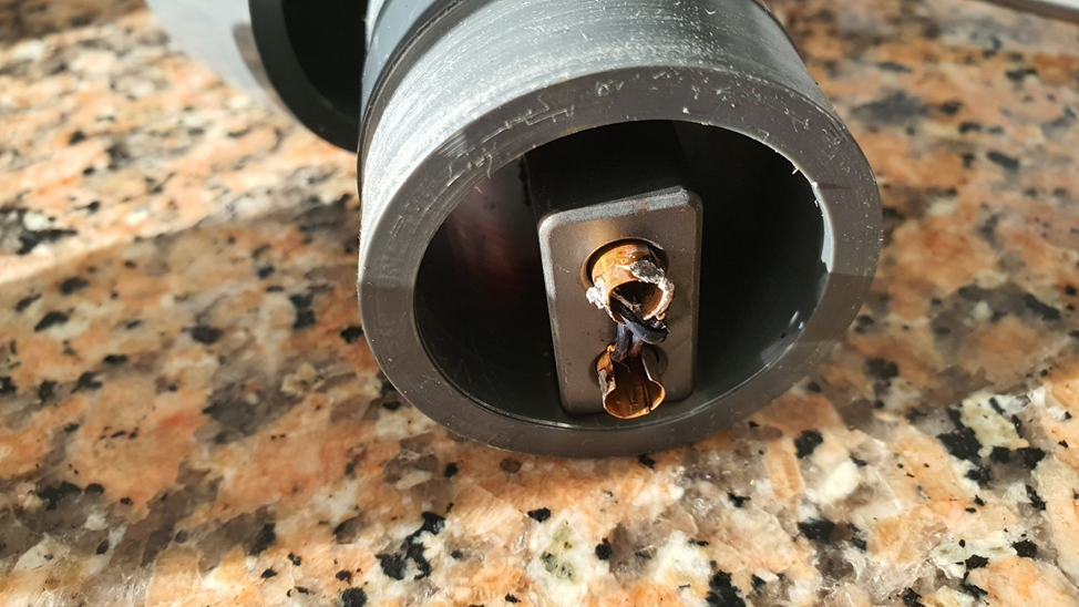
Ferrite core fused to enclosure’s wall.
When pulled, a chip was left adhered to the wall. These symptoms alone would mean temperatures higher than 150 ºC.
Charred wall with ferrite chip adhered.
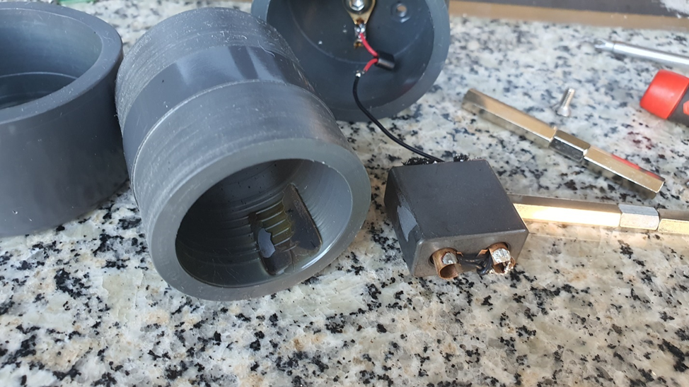
But Temperature was higher. There were found symptoms of solder melting, soaking the borders of foam packing pieces. Solder was an almost eutectic SN60-Pb40 alloy, so melting point was around 185 ºC. A respectable temperature. And core material should have been hotter.
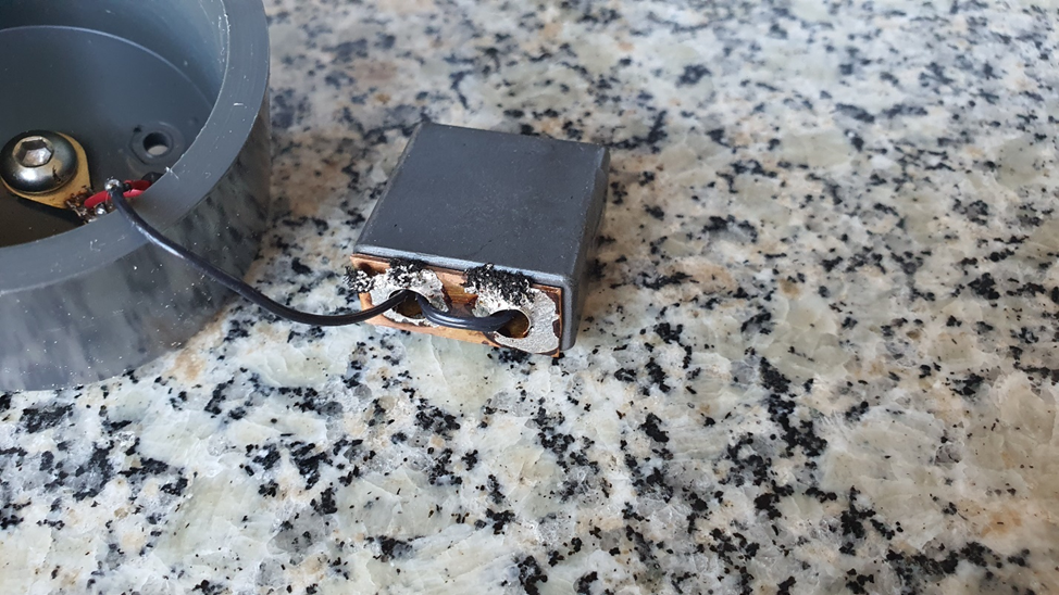
Melted solder, soaking packing foam.
Indeed, metallic parts were so hot that they softened PVC in contact with them. Among them were the spacers that held together the assembly and the grower washer in M6 stud.
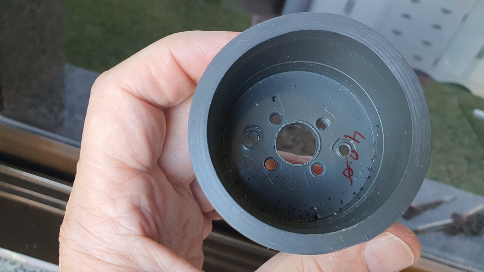
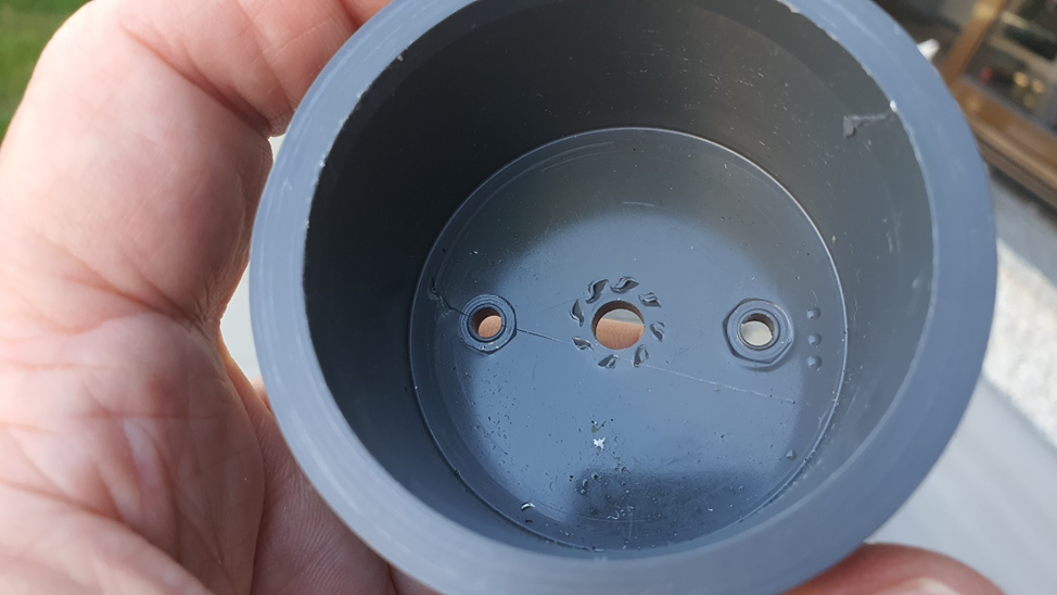
Imprints by hot spacers and Grower washer.
This caused a progressive (and accelerated) tilt in the 5 m tall aluminium radiator rod. To the point that the centre of gravity of the antenna moved outside of the legs’ enclosing triangle. Then it felt of the ground.
That the cores could reach such temperatures would provide an explanation for the SWR rising when using a BN-43 core (see section “Update 2024-06-19. BN-43 overheating.” in a previous post). In their datasheets, material 43 Curie temperature is declared as TC > 130 ºC, while for material 61 is TC > 300 ºC. If material 43 temperature rises above 140-150 ºC, its magnetic properties would change significantly, even to the point of a very reduced permeability. The issue should not arise with material 61. Soldered joints would fail before the core could reach its Curie temperature.
AutoT 6.25 was reassembled, including trueing spacers and bolts seats. It looks fine again, but now its limits are clearer. No more than 50 W when operating in FT8 for prolonged periods!
So, case closed (by now)! And back to the drawing board and the workshop when returning home!
Conclusions
- “On the air” tests allowed additional insights on the design and operation principle of Alpha and Chameleon’s “Matching devices”.
- It is possible broadband (3.5-50 MHz) operation with no adjustments and the help of any modern rig autotuner.
- However, it seems that the UNUN used in them has [possibly intentionally] high core loss. A significant portion of RF power would be dissipated in the core. Low SWR would not be the result of a correct matching, but of the equivalent loss resistance. Just like placing a resistor in parallel with the antenna. Only a fraction of RF power would be placed on the air.
- On tests with AutoT 6.25:
- Material 43 gives broader bandwidth but has higher core loss. And more important, lower Curie Temperature. It is adequate only for phone or CW operation at moderate power levels (100 W PEP). When operating FT8 for extended periods, QRP. Power should be lower than 25 W.
- 61-material can sustain elevated temperatures, but initial permeability and bandwidth are lower. It would be wise to try to keep it as cold as possible. If this material is used, a design including a heat diffuser and some kind of heatsink would be desirable.
- If using 61-material core, adding 7-8 turns, 40 mm diameter, 2.5 mm pitch coil in series with the antenna connection could improve bandwidth.
- PVC is not the best material for the enclosure. Its 80 ºC melting point is too low. A technical plastic with higher melting point should be used. Minimum Delrin, which melts at 165 ºC. Teflon melts at 327 °C but tends to be softer. PEEK, which melts at 343 °C, would be optimal.
- On the other hand, these devices make a convenient solution for casual broadband operation (preferably QRP, in view of their power ratings), with no adjustments needed in the antenna. But be ready to pay the toll in terms of low efficiency.
- Finally, the experience of building a duplicate of the whole system (Matching device, vertical rod, counterpoises) was time-consuming and needed machine tools and tooling not readily available at any ham workshop. At least a lathe and a vertical drill. If it is considered desirable operating such system, it would be advisable purchasing it from any reputable manufacturer (my personal advice would be Chameleon, if you can afford it).
About the author