
Foreword
When looking for an antenna appropriate for activities like SOTA, POTA, etc., short verticals always appear in the list. They also appear when looking for “reduced space” or “difficult ubications (AKA locations)” antennas. Like balcony-installed antennas when living in a Condominium.
Among them, a couple of products, sold as “Tactical antennas” look attractive, due to their presumptive ruggedness and easy deployment: Alpha’s “6-80M HF MIL 2.0 FMJ antenna + Mount” and Chameleon’s “CHA MPAS (Modular Portable Antenna System) 2.0”.
While Chameleon is honest, and states prominently that “This item is NOT suitable for military use. More ruggedized military versions of the products are available….”, Alpha isn’t so much, by including “MIL” in product’s name, military theme pictures, etc.
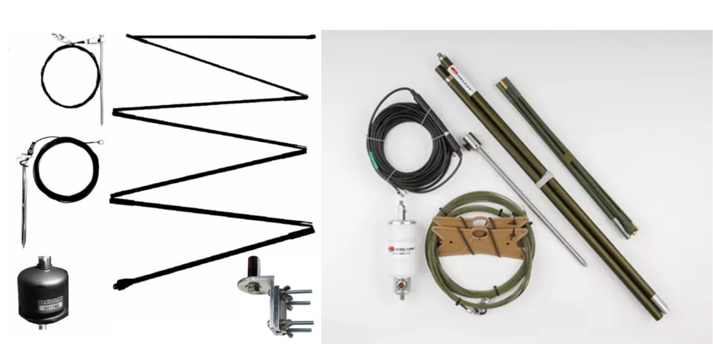
Alpha Antenna (left) and Chameleon (right) “Tactical” Antennas
Antennas’ design
The antennas are similar in design. They are composed of a “Whip”, a “Matching device” and a “Counterpoise”.
Whip
Both Alpha and Chameleon offer a foldable whip, in 7 sections, with a basic length around 2.850 m (Alpha: 2.845 m, Chameleon: 2.870 m).
In the case of Chameleon, it can be supplemented by an extender, 2.68 m long, for a total length of 5.55 m.
In the case of Alpha, it seems that longer models were available in the past. A fellow ham, Carlos – EA4HET, was so kind to lend a complete system for testing, which has a 10 section, 3.975 m long whip (Thanks Carlos!). Otherwise, it looks the same than the current model. Moreover, a length of wire (7.620 m), sold as “NVIS (Near Vertical Incidence Skywave) radiator” can be attached to the base of the whip (more on this later).
Counterpoise
It is simply a piece of wire, a grounding wire, or the body of a car.
In the case of Alpha, the counterpoise is supplied as a “Grounding kit”, composed of a 2.44 m long piece of wire and a ground rod. Curiously, in the case of Carlos’ antenna, it was supplied a 4.80 m long counterpoise. A stake for holding its end was included.
In the case of Chameleon, one to four wires, 6.35 m long, can be used as counterpoise, also with stakes at their ends.
Wire counterpoises are not used when whips are mounted on a car.
Matching device
These antennas, as any short vertical, need some kind of “matching device” to make them appear with an impedance in the operating range (usually SWR < 3) of the autotuners included in modern Ham transceivers.
Alpha’s is available as a standalone product at https://www.alphaantenna.com/product/auto-match/. Its description is:
“The AutoMatch enables touch free tuning on 10 through 80 meters when used with properly designed antennas. As an added benefit, an antenna tuner can even still be used, especially if your antenna is installed over a poor ground or near objects. This is especially useful if you have a disability such as being mobility impaired“
Can be used as a replacement match for properly designed antennas that include the MIL 2.0, FMJ, among others from Alpha including the HexTenna.
For example, when the AutoMatch is used with the HexTenna it enables touch free tuning on 10-80 meters in two easy steps shown here.”
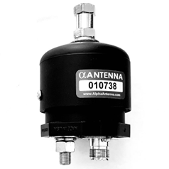
Alpha Antenna “AutoMatch”
Specifications:
Female 3/8 24 Hex Nut is on top and a 3/8 34 (sic) Bolt is on the bottom.
Power Rating: 250W PEP SSB, 125W CW, and 25W Digital
Chameleon’s is available at: https://chameleonantenna.com/shop-here/ols/products/cha-hybrid-mini/. Its description is:
“The CHA HYBRID SERIES Base is designed to enhance the capabilities of the common HF radio application by allowing faster tuning operation across the HF bands including MARS/CAP frequencies. This antenna base has an integral broadband impedance matching network (transformer 5:1) allowing broadband antenna tuning. An external antenna tuner is required to provide a low VSWR. The unit is water resistant.
Can be used with the CHA MIL 2.0, CHA MIL EXT 2.0, CHA CAP-HAT and CHA TACHAT…“
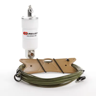
Chameleon’s CHA HYBRID MINI
Specifications:
Frequency: 6M – 160M
Power: 500W SSB PHONE, 100W CW, 100W HIGH DUTY CYCLE DIGITAL MODES
Mounting Configuration: 3/8-24 Thread”
However, under CHA MPAS 2.0 (https://chameleonantenna.com/shop-here/ols/products/cha-mpas-modular-portable-antenna-system-20) a lower rating is given for “High Duty Cycle Digital Modes”:
- HYBRID MINI-500w SSB Phone, 100W CW, 25W High Duty Cycle Digital Modes
A question on the difference was posed to Chameleon and quickly answered by Don Sherman, W7SSB:
“To be safe keep digital at 50 watts if running for long periods!”
Therefore, I’d retain the 50 W rating. And possibly less.
Matching device analysis
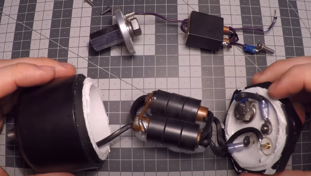
A fellow ham crack-opened both Matching devices and reported his findings in a YouTube video: https://youtu.be/4n30XykCChY?si=5zc6Fwe7f886NLBN.
He started by Chameleon’s. The housing is built from CNC-machined materials (Aluminium alloy for top and bottom sections, technical polymer-reportedly Delrin- for the central body). Inside, the “matching device” reduces to a simple UNUN. He didn’t make any measurement, but some insights can be extracted from the video. Most important are:
1.- The UNUN is simply an autotransformer, with one-turn primary and total 2.5 turns. The primary is made of copper tubing with a shorting plate in the side opposite to transceiver’s connections. Inside it is coiled a… 1.5 turn! winding. This “feat” is accomplished by threading the last turn back in the same aperture by which the wire came.
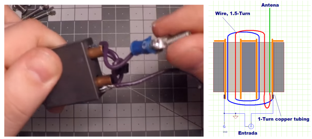
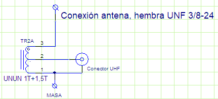
Chameleon’s CHA HYBRID MINI transformer (left) and winding diagram (right)
2.- The UNUN is built on a large binocular core. Most probably from FairRite. Cores of such large size are offered only in material 43 (μi = 800), ref. BN-43-7051 and 61 (μi = 125), ref. BN-61-002. Both are used in output transformers of HF Power Amplifiers delivering 100-120 Wats CW. So, why not in an UNUN? Regarding the material used in Chameleon’s UNUN, in the absence of inductance measurements, only an educated guess can be made. From the shine of the core, it looks more like a BN-43-7051. A higher permeability core would perform better in the lower bands, in despite of higher core loss at high frequencies. Finally, higher core losses would improve SWR…. apparently (more on this later).
The schematics is simple:
Chameleon’s CHA HYBRID MINI schematic diagram
With:
1 to 2: 1 turn
2 to 3: 1.5 turns
1 to 3: 2.5 turns
This arrangement has some interesting features:
- Turns (voltage) ratio is 2.5:1.
- Impedance transformation ratio is 6.25:1.
- The forth and back arrangement of the last turn adds some stray/parasitic inductance. It seems that this “feature” is intentional. It may help to compensate for the capacitive behaviour of electrically short antennas (more on this later).
However, none of the above values correspond to the advertised transformation ratio value (transformer 5:1). Why? Erratum or intentional diversion? This question will remain unanswered. There is not enough data to elucidate!
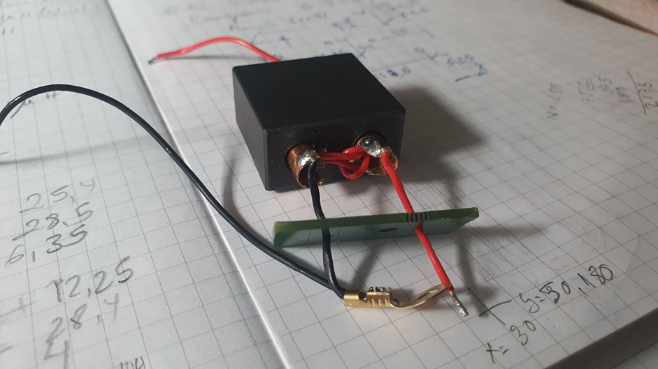
Alpha: Electrically, it looks identical to Chameleon’s: It is an UNUN, with the same turns’ ratio and schematic. However, construction is sloppier, using ferrite toroidal cores threaded in copper tubing, closing the first turn with thick solid wire. The arrangement of secondary wiring is the same than that of Chameleon’s.
Alpha Antenna AutoMatch transformer
The enclosure is made from cheap USA-standard PVC plumbing fittings. The description includes sentences as “Alpha Match constructed in a polyvinyl chloride housing” and “The AutoMatch is computer designed for proper balance. It contains a transformer that is enclosed in a rugged housing. The match and elements are what give the AutoMatch both the inductive and capacitive balance. Once the elements are installed, their capacitive characteristics also enables RF to radiate.” These assertions look… emmm… somehow like… mountebank speech?
Finally, the power ratings of Alpha are in general lower than Chameleon’s:
Table 1: Alpha Antenna AutoMatch and Chameleon’s Cha Hybrid Mini power ratings.
| SSB (W PEP) | CW (W) | FM/Digital (W) | |
| Alpha | 250 | 125 | 25 |
| Chameleon | 500 | 100 | 50 |
Especially interesting is the FM and digital modes rating. Alpha’s 25 W figure looks too low. However, in view of the overheating detected in later transmission tests, it could be the right rating.
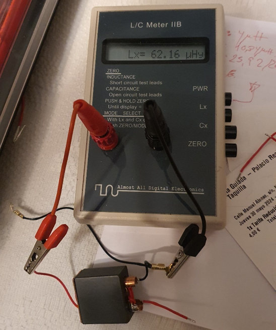
Now, some measurements. To check the hypothesis about turns ratio, inductance measurements, open circuit, were taken on Carlos’ “Alpha Match” or “AutoMatch”. An L/C meter IIB from AADE (Almost All Digital Electronics, RIP-SK) was used. It is not as accurate as a professional instrument, but it is sufficient for the intended purpose. Results are summarized in Table 2.
Table 2: Inductance of Alpha Antenna AutoMatch. Raw measurements.
| Measuring points | Inductance (μH) |
| In (1-2) | 4,048 |
| Out (2-3) | 10,35 |
| Total (1-3) | 26,06 |
From college physics, it could be expected that inductance would be proportional to the square of the number of turns. However, this is not exactly the case. Nevertheless, results can be explained by the presence of stray inductances. A possible model of the device is:
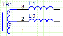
Where L’0 and L’1 represent the stray inductances. With the above measurements, and assuming the hypothesis of a 2.5:1 turns ratio, it is possible to compute the values of actual inductance of the windings and of stray inductances. Results are given in Table 3.
Table 3: Inductances of Alpha Antenna AutoMatch. Estimation of stray inductances.
| UNUN Alpha Antenna AutoMatch | Stray Inductance (μH) | ||||
| Measuring points | Measured Inductance (μH) | Actual inductance (μH) | Turns Ratio | L’0 | L’1 |
| In (1-2) | 4,048 | 3,948 | 0,1 | ||
| Out (2-3) | 10,35 | 8,89 | 1,50 | 0,1 | 1,36 |
| Total (1-3) | 26,06 | 24,70 | 2,50 | 1,36 | |
(turns ratios were computed as the square root of actual inductance ratios)
For the sake of comparison, a couple on UNUN to the above design were constructed. One was wound on a BN-43-7051 core, the other on a BN-61-002.
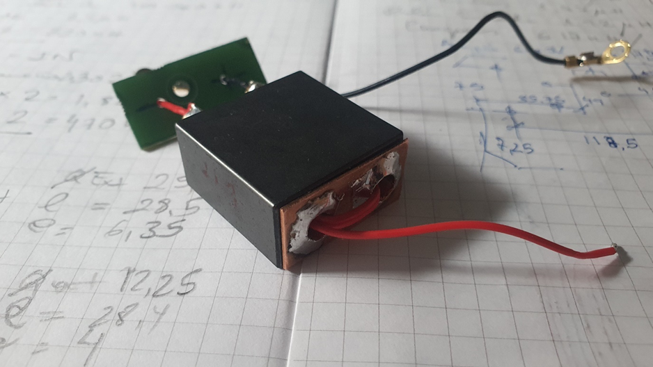
UNUN built on a BN-43-7051 core
Results (measured inductance) were comparable to Alpha’s, after accounting for the different permeabilities of the ferrites used.
Measuring inductance on the UNUN built on a BN-43-7051 core
Table 4: Inductances of the UNUN built on a BN-61-002 core. Estimation of stray inductances.
| UNUN on BN-61-002 core | Stray Inductance | ||||
| Measuring points | Measured Inductance (μH) | Actual inductance (μH) | Turns Ratio | L’0 | L’1 |
| In (1-2) | 1,075 | 1,055 | 0,02 | ||
| Out (2-3) | 2,94 | 2,37 | 1,50 | 0,02 | 0,55 |
| Total (1-3) | 7,14 | 6,59 | 2,50 | 0,55 | |
Table 5: Inductances of the UNUN built on a BN-43-7051 core. Estimation of stray inductances.
| UNUN on BN-43-7051 core | Stray Inductance | ||||
| Measuring points | Measured Inductance (μH) | Actual inductance (μH) | Turns Ratio | L’0 | L’1 |
| In (1-2) | 9,638 | 9,488 | 0,15 | ||
| Out (2-3) | 24,37 | 21,32 | 1,50 | 0,15 | 2,9 |
| Total (1-3) | 62,16 | 59,26 | 2,50 | 2,9 | |
It must be noted that in the case of Alpha Antenna AutoMatch, ferrite’s permeability is an unknown. However, from the inductance values, it should be between those of material 61 and material 43. Curiously, this intermediate value is found in many unbranded Chinese ferrite cores supplied with HF Power Amplifier kits.
Preliminary conclusions
The above results are totally compatible with the proposed hypothesis about “Matching devices” structure.
| We can conclude that both Alpha and Chameleon matching devices reduce to an UNUN with 2.5:1 turns ratio, designed to add some stray inductance to the antenna circuit. |
Such UNUM will make 50 Ω in the transmitter side to appear as 312.5 Ω in the antenna side.
Final note: Palomar Engineers offer a similar device under “The Bullet” trademark. It is intended for long wire antennas, and useful information is provided on their website (https://palomar-engineers.com/tech-support/tech-topics/best-hf-end-fed-antenna/). Externally, it is similar to Alpha’s: Constructed from USA-standard PVC pipe fittings and hardware available at any ironmonger’s shop. Internally, it seems to contain a 3:1 turns ratio UNUN (9:1 Z ratio).
About the author