
Antennas use cases
It seems that, in despite of the similarities in the matching devices, the intended use arrangement is different for Alpha and Chameleon. At least in the manuals.
Alpha calls for installing the NVIS radiator horizontally, one end attached to the base of the whip (and to the output of matching device), and the other held by a stake. Therefore, the antenna is more an off-centre-fed radiator than a proper vertical. The counterpoise is the real ground, electrically connected through the grounding rod and attached wire.
Chameleon instructions include operation as a genuine end-fed vertical. Depending on the operation bands, it could be necessary to add the extender. Recommended counterpoise is a set of one to four wires, 6.350 m long, its end held in place by stakes.
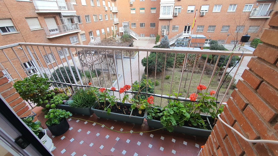
However, for comparing performance, it would be necessary to define a fixed (constant) test layout. Moreover, a layout like the one I would use would be a convenient election. For this reason, a balcony-mounted setup with a 4.8 m counterpoise (Same length than Carlos’ Alpha) was selected.
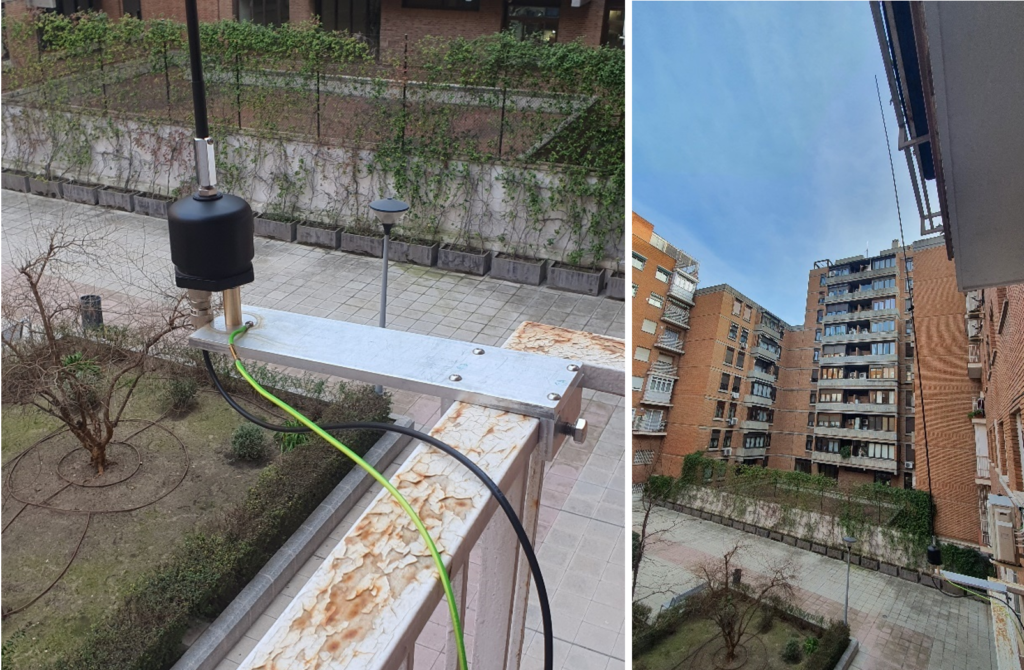
AutoT was attached to the balcony using an intermediate Aluminium alloy flat bar. In some tests, balcony railings were connected to ground as additional counterpoise, and some interesting results were obtained.
SWR. Alpha system VNA measurements
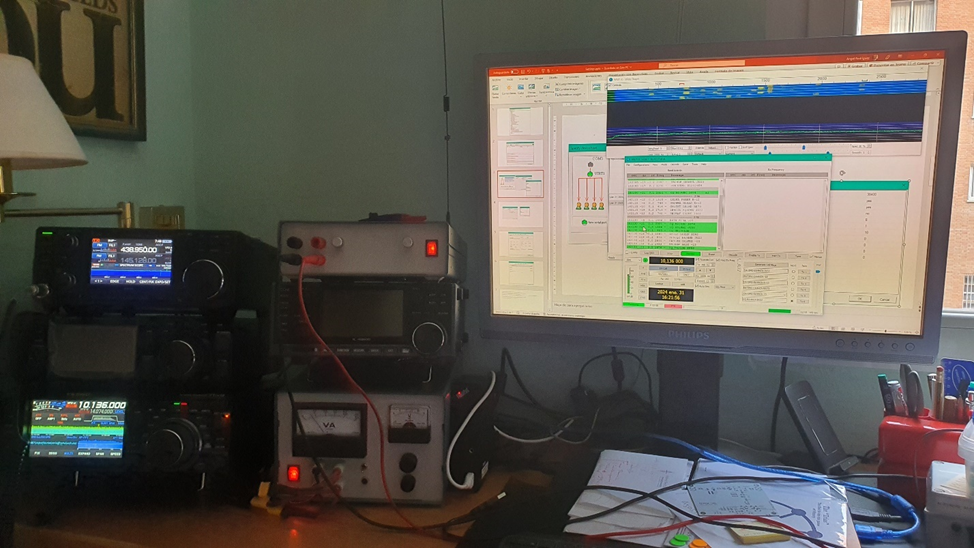
The antennas were measured from the shack. Cable to the antenna was RG-58, 5 m long in Alpha’s initial measurements. Later, it was replaced by RG-142, with a short length of RG-316 for passing a window.
Measurements were taken with a Mini VNA Pro by Mini Radio Solutions and BlueVNA software for Android. The VNA was calibrated directly on the DUT port (Intentionally, no cable compensation was made, as the purpose was to measure impedance and SWR as seen by the transceiver). Therefore, readings included impedance changes caused by the coaxial cable. Data was exported in csv format. Screenshots were taken for the sake of a quick analysis.
Tests were started on Alpha antenna system. In a first stage, only the AutoMatch and counterpoise were installed. It must be noted that electrical contact with balcony railing was not guaranteed.
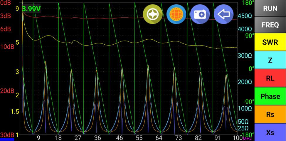
Alpha AutoMatch with counterpoise, without whip.
In these conditions, a high, but not too high -SWR between 3 and 5- was observed above 40 m band. Also, periodic resonances due to the coaxial cable can be observed.
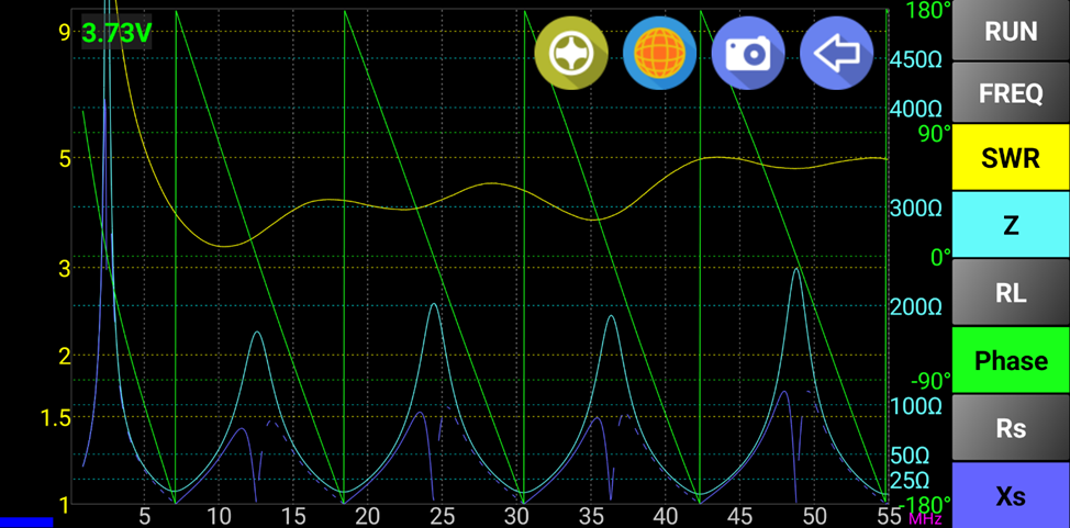
Alpha AutoMatch with counterpoise, without whip. SWR readings.
Then the whip was installed.
Alpha AutoMatch with whip.
Initial measurements didn’t look promising in the lower bands (1.8 and 3.5 MHz): SWR was above 3, the maximum theoretical range of FTDX10 autotuner. However, it could find a tuning solution, reaching less than 1.3 SWR in both bands. In higher bands, up to 70 MHz, there was no issue.
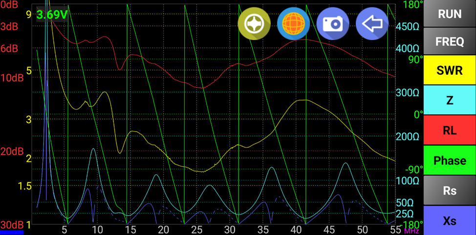
Alpha Antenna System. MiniVNA Pro screenshot.
FT-8 reception was good, but no contacts were made. Then, the antenna was packed carefully, to be returned to Carlos at the earliest opportunity.
FT8 reception with Alpha Antenna System.
SWR. AutoT 6.25 VNA measurements
A few months later, it was started the construction of the prototype of AutoT 6.25 UNUN. When completed, it was tested with the counterpoise alone and then with four radiators: A 1.8 m telescopic. An aluminium tubing one, 2 m long. A brass tubing one, 3 m long. And an aluminium tubing one, 3.88 m long. In this case, a good connection between electric ground and balcony railing was established.
Counterpoise alone results were similar to Alpha’s (when comparing graphs, note the difference in frequency span).
AutoT 6.25. Counterpoise only readings.
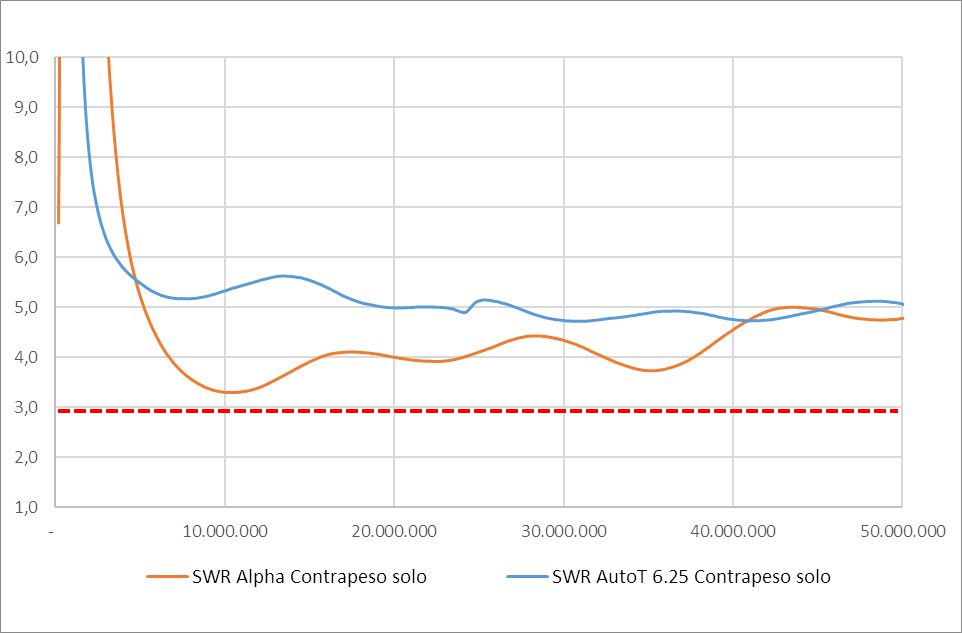
Alpha and AutoT 6.25 comparison. Counterpoise only readings.
As it could be expected, for the 3.88 m radiator, results were similar to Alpha’s. For shorter radiators, the cutoff frequency (defined as that for which SWR = 3) was higher. The shorter the length, the higher the cutoff frequency. No surprises!
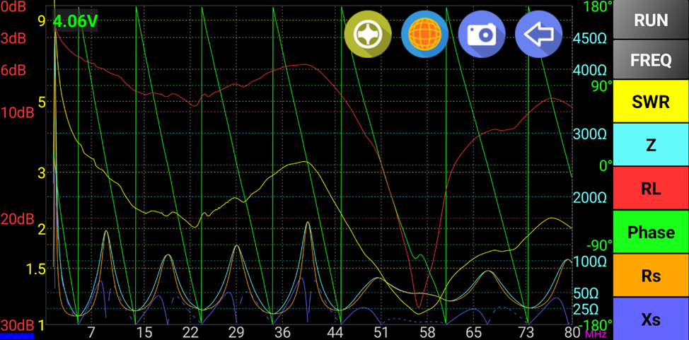
AutoT 6.25 with 3.88 m radiator. MiniVNA Pro screenshot.
Data was imported into an Excel spreadsheet, which allowed preparing comparative graphs.
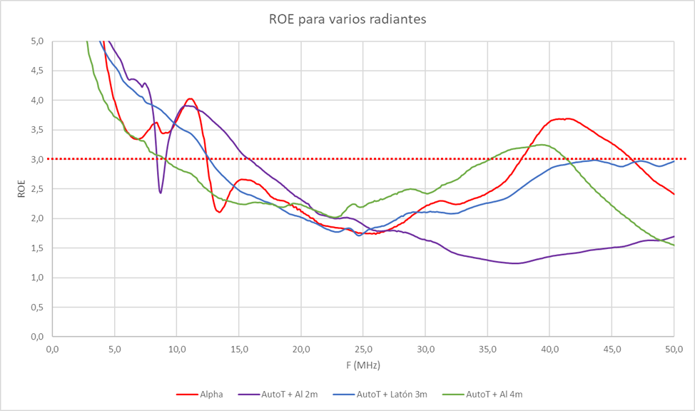
AutoT 6.25. SWR graphs comparison for several radiators.
The only apparent anomaly was the rise in Alpha’s SWR between 7 and 12.5 MHz. It could be explained by the bad connection from ground to balcony railing when testing it.
To test this hypothesis, ground was disconnected from the railing. The SWR graph changed, becoming more similar to that of the original Alpha (although in general better, with lower SWR!).
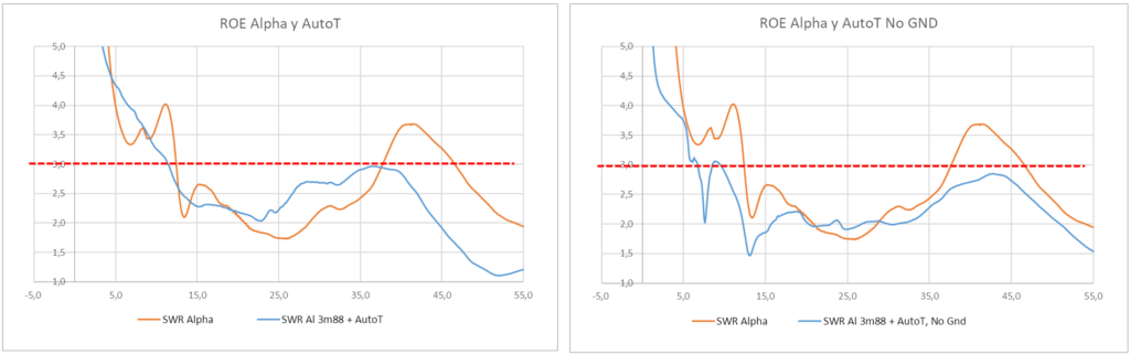
SWR graphs comparison. Left: Ground to railing. Right: Isolated railing.
Ground-railing connection made the graph smoother, and gave less SWR in 50 MHz, at the cost of higher SWR in 7 and 28 MHz and higher cutoff frequency. Not an interesting trade-off!
Some additional tests were carried out using a 5 m long Aluminium radiator. Up to 20 MHz results were slightly better than for 3.88 m radiator. Between 20 and 32 MHz, it was the opposite. And above 32 MHz, there was a continuous crossing, with the 5 m radiator performing better in 50 and 70 MHz bands. Overall performance in HF bands -measured in terms of SWR readings- was slightly better for the shorter radiator.
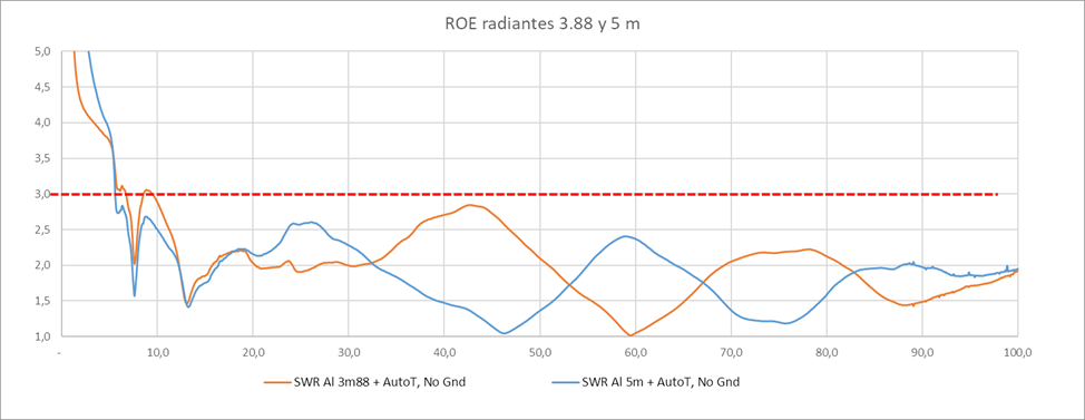
SWR graphs comparison. 3.88 m and 5 m radiators.
About the author